 Nuclideon
 Scene Explorer
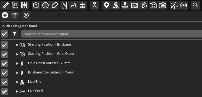
The Scene Explorer window lists the assets currently in your scene.
Action Bar

The buttons across the top of the Scene Explorer allow quick access to add or remove items from the scene.
 Add Folder Adds a folder to the Scene Explorer. This can help with organising your scene.
 Remove Selected Deletes all selected items from the scene.
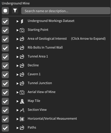
Scene Items
The area below the quick menu displays the items in the scene.
Project Settings

Click the icon to open the project settings menu. The project name is also displayed here.
Show All Items
![]() Click the icon to show all items listed/filtered in the Scene Explorer. Sub-nodes under a folder will also be displayed automatically (even in the collapsed state).
Click the icon to show all items listed/filtered in the Scene Explorer. Sub-nodes under a folder will also be displayed automatically (even in the collapsed state).

Hide All Items
![]() Click the icon to hide all items listed/filtered in the Scene Explorer. Sub-nodes under a folder will also be hidden automatically (even in the collapsed state).
Click the icon to hide all items listed/filtered in the Scene Explorer. Sub-nodes under a folder will also be hidden automatically (even in the collapsed state).
Selecting Items
Click on an item in the Scene Explorer to select it. Selected items will appear highlighted.
You can select multiple items in the Scene Explorer by holding Ctrl and then left-clicking them individually, or shift-clicking to quickly select larger groups. Doing this on an already-selected item will deselect it.
Single clicking without Ctrl will deselect all items and select only the item you clicked.
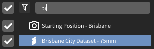
Filtering Items
Items listed in the Scene Explorer can be filtered by name or type using the controls above the list. Items that are filtered out will not be selected when performing a shift-click selection (see above).
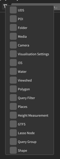
By type:
![]() Click this icon to open the filter-by-type menu.
Click this icon to open the filter-by-type menu.
Filtered items:
By name (case-insensitive):
Reorganising the Scene
Items or groups of items in the Scene Explorer can be reordered by holding left-click and dragging them. A blue line indicates where the item(s) will land after you release.
Loading UDS Models
There are two ways to add models to the scene.
- Drag and Drop
- On devices with a file explorer you can drag a file from your file explorer and drop it in the scene window to add the model to the scene.
- Direct URL Loading
- You can type a URL or path in the
 "Add Scene Item" popup. The path field at the top of the pane accepts URL and network paths to retrieve UDS files.
Scene Item Properties
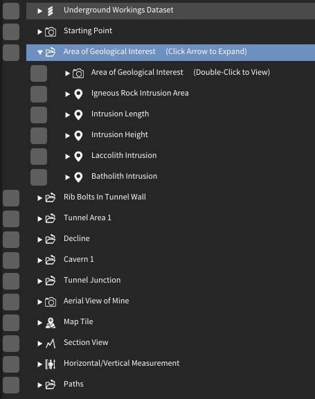
Items in the Scene Explorer (see Scene Items) can be expanded to show additional information. The type of information displayed depends on the scene item type.
UDS Point Cloud
The expanded properties for UDS files show the path the UDS was loaded from and a tree view of the internal metadata from the file.
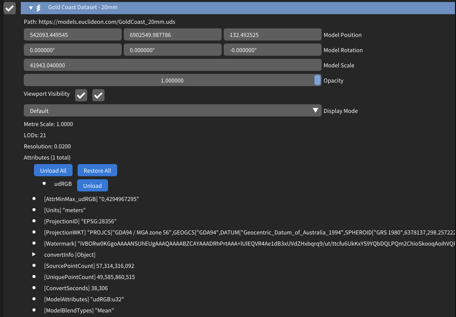
The system displays advanced information such as the attributes in the file, their sizes, and how they are blended for level-of-detail calculations.
Comparing Models
You can compare two models currently loaded in the scene that were scanned at different times. The model you select in the Scene Explorer will be the model that has a distance calculated from each point to a mesh of the comparison model. Note that this process will generate a third model representing the comparison between the two input models.
- Right-click on a model in the Scene Explorer.
- Select the Compare Models option.
- Enter the required information: a. Model to compare against. When comparing models from two different dates, this should be the older of the two models. b. Ball radius (in metres). Used to mesh the point cloud. This should be the maximum distance between two points that could be considered part of the same surface. c. Grid size (in metres). Used to split the model into smaller pieces for processing. This is the maximum distance a point can be from a point in the old model; points that sit outside all grids will be displayed with the "No Match" colour when using the displacement visualisation options.
- Click the Compare Models button. This will create a convert job and open the Convert window. See the Convert section for more information.
Export using udCloud
You can export a UDS, LAS, or OBJ file if it is loaded via URL in udCloud rather than from disk.
- Right-click on a model in the Scene Explorer.
- Select the Export Pointcloud option to open the Export Pointcloud modal.
- Enter a filter (optional) and output filename.
- Click the Export using udCloud button to save the model to udCloud.
The export occurs in udCloud and will continue even if udStream is closed. When the export is complete, you will receive a confirmation email.
Workflow
 Show/Hide Scene Explorer: Toggle the scene explorer window.
 Selection Tool is the default tool when no other tool is active. It allows you to select items in the scene.
 Share Project: If the current project is saved on the cloud, you can share it with others.
 Convert Opens a popup to convert datasets into the UDS format.
Menu Bar

 Profile Menu: Access your profile, change password, export project, sample projects, or log out.
- File: Options to open/save scene.
- Edit: View or change scene settings/preferences.
- Window: Toggle fullscreen mode (Hotkey: F5).
- Help: Options to open support in browser, show user guide, and show mouse controls.
- Tools: Displays tool icons.
Tools
udStream has a range of tools to help with your workflow.

 Line Measurements (see Measuring)
 Area Measurements An Area Measurement is used to measure the horizontal area described by 3 or more points. The function is almost identical to the Line Measurement; the only difference is that the resulting polygon is closed by default.
 Height Measurements The height measurement tool is useful when you wish to measure the height and horizontal distance between two points. Click the height measurement tool from the tool bar, then click a point in the scene, then click a second point to anchor the height measurement.
 Box Filter Adds a box filter to the scene.
 Sphere Filter Adds a sphere filter to the scene.
 Capsule Filter Adds a capsule filter to the scene.
 Cross Section Adds a cross section to the scene.
 Section View Adds a section view to the scene.
 Add View Shed Adds a viewshed to the scene.
 Single Annotation Point You can add multiple annotation points to the current scene and alter the name and colour of each. Click the annotation button in the tool bar and click in the scene to place one. Clicking on the annotation in the Scene Explorer will give you options to change the size and colours of the displayed text. Right-clicking on the annotation name in the Scene Explorer will bring up a context menu where you can edit the name, move the camera to the annotation, or remove it.
 Add Map Tile Adds a new Map Tile to the scene.
 Add Place Layer Adds a new Place Layer to the scene.
 Add Media Adds a media node to the scene.
 Add Flythrough Adds a new flythrough to the scene.
 Save Current Camera Saves the current camera position and rotation as a viewpoint.
 Save Current Camera with Visualisation Settings Saves the camera as above, along with the current visualisation settings.
 Add GTFS Adds a new GTFS to the scene.
 Add Live Feed Adds a new Live Feed to the scene.
 Voxel Inspector Allows you to inspect the data associated with individual voxels of a UDS file.
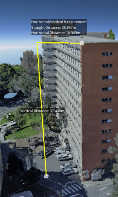
(Above) Height measurement tool
Edit Spatial Reference
You can edit the Spatial Reference to override the zone information of the scene. The Edit Spatial Reference button is visible in the status bar at the bottom of the scene viewport.
![]()
This opens the Edit WKT modal, where you can specify the SRID and WKT information.
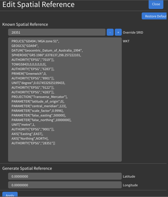
- Override SRID Enter an SRID to override the current one.
- WKT The Well Known Text representation of the SRID.
- Latitude and Longitude Change the latitude and longitude of the origin and central meridian of the projection.
Compass
![]()
Clicking this button will face the camera north.
Return Camera
![]()
Returns the camera to the initial starting view.
Lock Altitude
![]()
Hotkey: Space
Keeps the camera's height constant (Z-axis lock) when panning with the mouse or strafing with the keyboard.
Toggle Viewport
![]()
Opens a second view that can be controlled independently or used to display a top-down map view that is synchronised with the main viewport.
Visualisation Settings
![]()
A shortcut to open the Visualisation section in Settings.
3D / Tracking
![]()
This opens the 3D / Tracking modal, where you can specify the stereoscopic screen coordinates, stereoscopic mode, and VRPN information.
![]()
- Screen Coordinates The XYZ coordinates of the bottom-left, bottom-right, and top-left of the screen in tracking space.
- Stereoscopic Mode The stereoscopic display mode of udStream.
- Enable VRPN Enables VRPN (Virtual-Reality Peripheral Network) to interface with virtual reality peripherals.
![]()
- Reset Origin Resets the tracking origin point.
- Restore Previous Configuration Reloads the previous device configuration.
- Add Device Add a new VR device for tracking. Clicking this opens the following section:
![]()
- Device Type The tracking type of the device.
- Control Type The object the device is performing tracking on.
- Device ID / Host Name The ID and host name of the device being used.
- Add Device Confirm, create, and apply the tracking device.
Image POI
To add an image at a specific location, drag and drop a PNG, JPG, or TIFF file into the scene.
- Image Type Use Image Type to select how you want the image to be displayed:
- Standard will display the image as a billboard, always facing the camera.
- Orientated Image will allow you to change the orientation of the image.
- Panorama will project the image onto a panoramic cylinder.
- Photo Sphere will project the image onto a sphere.
- Thumbnail Size The size the image will be displayed at in the scene.
- Reload Time (secs) Controls how often the image is refreshed in the scene. This is useful when the image changes over time and should be updated periodically.